🔋 Shunt Reactors and Capacitor Banks in Substations: Voltage Control, Reactive Power, and Harmonic Filtering
By ElectroGuide.tech
📅 Introduction
Power quality is a critical aspect of modern substations, especially with increasing grid complexity and distributed energy sources. Among the key tools used for maintaining voltage stability and improving reactive power balance are shunt reactors, capacitor banks, and harmonic filters. This article explores the application, design considerations, and importance of these components in ensuring efficient and stable power system operations.
⚡ What is a Shunt Reactor?
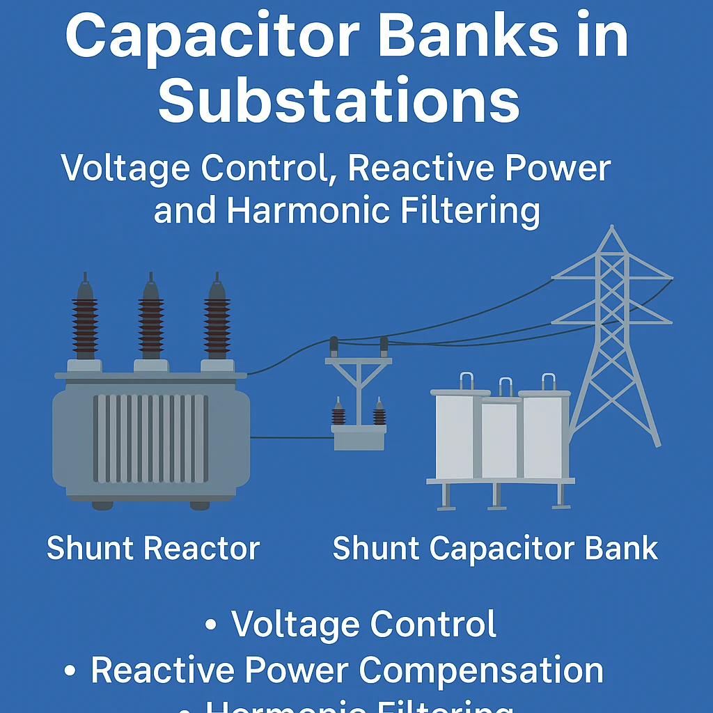
A shunt reactor is an inductive device used in substations to absorb reactive power and suppress overvoltages, particularly under light load or no-load conditions. Unlike transformers, reactors do not transfer power but are mainly used for voltage regulation by controlling the reactive power flow.
💪 Applications of Shunt Reactors in Power Substations
Shunt reactors are commonly installed:
- At the ends of long transmission lines
- On busbars in EHV and UHV substations
- In underground cable systems where capacitive charging current is high
Their primary function is to absorb excess reactive power generated due to line capacitance, thereby preventing undesirable voltage rise.
📈 Voltage Rise in Light Load Conditions
This phenomenon, known as the Ferranti effect, causes voltage at the receiving end of a long transmission line to rise above the sending end under light or no-load conditions. Shunt reactors counteract this by consuming inductive reactive power, keeping voltage within acceptable limits.
🔹 Controlled vs Fixed Shunt Reactors (MCSR)
- Fixed Shunt Reactors: Constant inductive reactance; less flexibility.
- Magnetically Controlled Shunt Reactors (MCSR): Allow variable inductance by controlling the magnetic flux path; offer better control and reduced switching operations.
Benefits of MCSR:
- Dynamic voltage control
- Lower switching transients
- Improved flexibility in grid operation
⚙️ What is a Shunt Capacitor Bank?
A shunt capacitor bank is a group of capacitors connected in parallel to provide leading reactive power. They improve voltage profile and reduce line losses by compensating for inductive loads.
🔄 Role of Shunt Capacitors in Reactive Power Compensation
Capacitor banks:
- Improve power factor
- Reduce I²R losses
- Minimize transformer loading
- Support system voltage during high demand
They are especially effective in distribution substations and industrial plants.
📍 Optimal Placement of Shunt Capacitor Banks
Effective placement is critical:
- At feeder level: Improves local voltage and reduces losses
- At substation bus: Supports bulk reactive compensation
- Distributed placement: Better overall system efficiency and voltage control
🔊 Harmonic Distortion in Substations
Harmonics are generated by nonlinear loads such as:
- Variable Frequency Drives (VFDs)
- Inverters
- Electronic converters
Impact:
- Overheating of equipment
- False relay operation
- Resonance with capacitor banks
🛠️ Harmonic Filters: Need, Types, and Function
To protect capacitor banks and sensitive equipment, harmonic filters are installed:
Types:
- Passive filters: Tuned filters, high-pass filters
- Active filters: Detect and cancel harmonics dynamically
- Hybrid filters: Combination of both
Functions:
- Block or absorb specific harmonic frequencies
- Prevent resonance conditions
- Maintain waveform quality
🛡️ Importance of Filtering in Capacitor Banks
Capacitor banks are susceptible to harmonic amplification and resonance. Installing filters:
- Prevents dielectric stress
- Increases capacitor lifespan
- Ensures reliable operation
⚠️ Challenges: Resonance, Overvoltage, and Protection
Designers must consider:
- Series and parallel resonance conditions
- Overvoltage protection using surge arresters
- Coordination with protective relays and CT/VT ratios
📊 Design Considerations for Shunt Reactors and Capacitor Banks
- Voltage and current ratings
- Insulation coordination
- Switching transients
- Space and cooling requirements
- Detuning factor in harmonic filter design
🔄 Comparison: Shunt Reactor vs Shunt Capacitor Bank
| Parameter | Shunt Reactor | Shunt Capacitor Bank |
|---|---|---|
| Function | Absorbs reactive power | Supplies reactive power |
| Usage | Voltage suppression | Power factor improvement |
| Harmonic Concern | Minimal | High; needs filtering |
| Placement | Long line, EHV bus | Load center, substation bus |
| Impact on Voltage | Reduces voltage | Boosts voltage |
🧬 Conclusion: Integrated Power Quality Solutions
Shunt reactors and capacitor banks serve complementary roles in managing reactive power and maintaining voltage stability in substations. When harmonics are present, properly designed filters ensure safe and efficient operation. A holistic design approach enhances system reliability, efficiency, and equipment life.
🤔 FAQs
Q1: What is the purpose of a shunt reactor in a substation?
To absorb reactive power and suppress voltage rise under light-load conditions.
Q2: Can shunt reactors and capacitor banks be used together?
Yes, but careful design is needed to prevent resonance and manage switching transients.
Q3: How are harmonics filtered in capacitor banks?
Using tuned passive filters, active filters, or hybrid systems to eliminate targeted harmonic frequencies.
Q4: What is the detuning factor in capacitor bank design?
A safety factor used to shift the natural frequency away from dominant harmonic frequencies to prevent resonance.
Как выбрать источник бесперебойного питания, получите информацию.
Рейтинг лучших ИБП, в нашем блоге.
Почему стоит купить ИБП, узнайте.
Рекомендации по выбору источников бесперебойного питания, читайте.
Все о ИБП, узнайте.
Покупка ИБП: на что обратить внимание, в нашем блоге.
Ваш идеальный ИБП, здесь.
Технические аспекты ИБП, читайте.
Советы по использованию ИБП, получите советы.
Что нового в мире ИБП, узнайте.
Правила подключения источника бесперебойного питания, узнайте.
Как выбрать ИБП для разных нужд, читайте.
Как выбрать оптимальный ИБП, читайте.
Рейтинг популярных источников бесперебойного питания, читайте.
Как установить источник бесперебойного питания?, в нашем материале.
Идеальные решения для бесперебойного питания, ознакомьтесь.
Как продлить срок службы ИБП, получите советы.
Как выбрать ИБП для игры, ознакомьтесь.
Что учесть при выборе источника бесперебойного питания, здесь.
ИБП http://www.istochniki-bespereboynogo-pitaniya.ru/ .