In the vast world of electrical power systems, accuracy and safety are paramount. One of the essential devices ensuring both is the Potential Transformer (PT), often referred to as a voltage transformer. From monitoring high voltages in substations to feeding precise input to protective relays and meters, PTs play a crucial role. This article explores the working principle, types, applications, and specifications of PTs, and also compares PT vs CT (Current Transformer) for a comprehensive understanding.
What is a Potential Transformer?
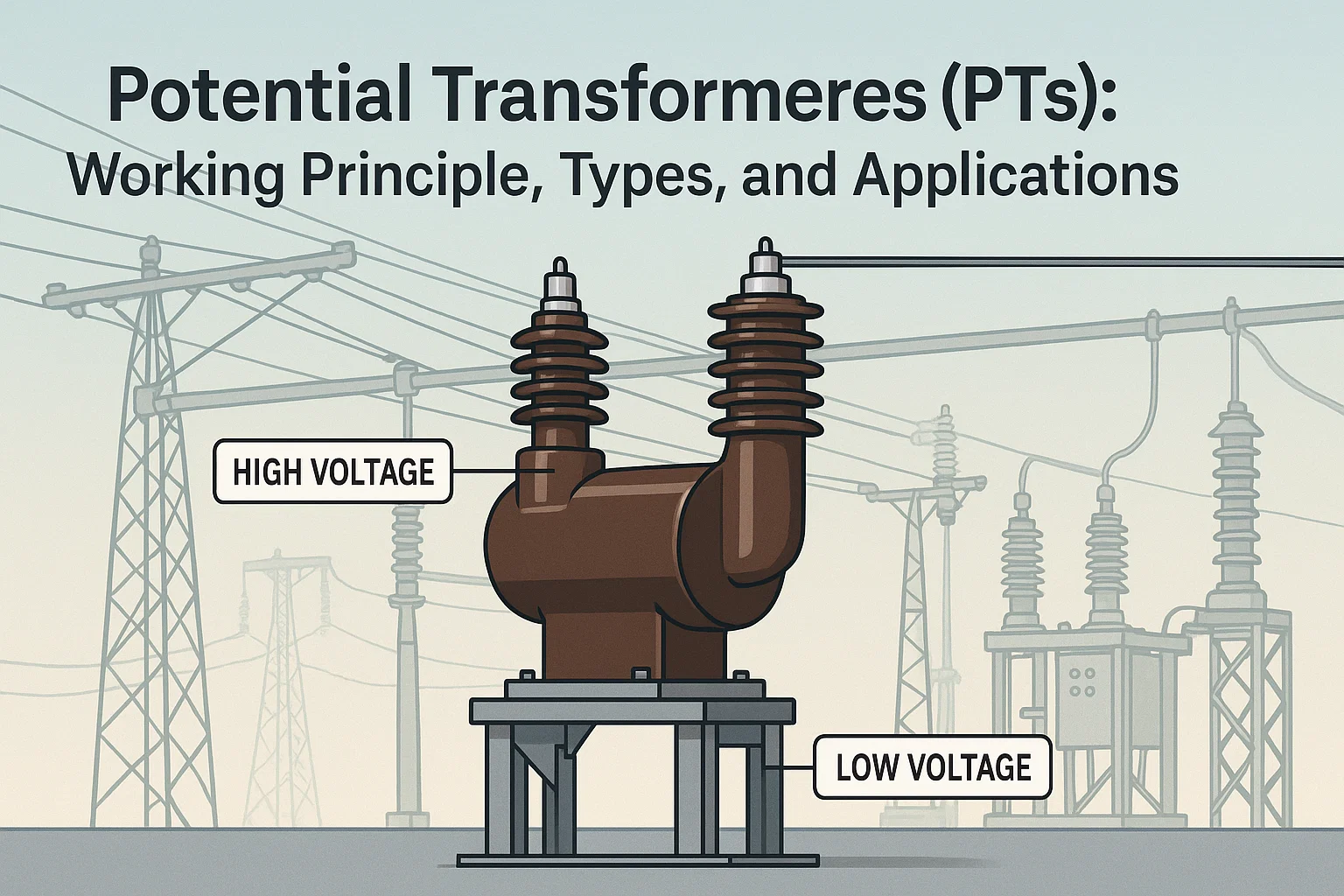
A Potential Transformer (PT) is a type of instrument transformer used in electrical engineering to step down high voltage to a lower, standardized voltage level that can be safely used for metering and protection. The stepped-down voltage maintains the same phase angle and proportional relationship with the primary system voltage, allowing devices like voltmeters, energy meters, and protective relays to work efficiently without exposure to high voltages.
Working Principle of Potential Transformer
Basic Concept
A PT operates on the same principle as any conventional transformer—electromagnetic induction. It is a voltage step-down transformer designed to deliver an accurate, scaled-down replica of the primary system voltage to the secondary side.
Phasor Diagram Explanation
Understanding PT operation requires a look at its phasor diagram, which illustrates how the voltages and currents behave in an ideal and practical PT.
- Primary Voltage (Vp) is applied to the primary winding.
- A small excitation current flows in the core, generating a magnetic flux (Φ).
- This flux induces a voltage Vs in the secondary winding through mutual induction.
- In an ideal PT, Vs is in phase with Vp and proportional based on the turns ratio (Np/Ns).
- In practice, due to core losses (hysteresis and eddy currents), there is a slight phase shift and voltage ratio error.
This is where accuracy class becomes critical, especially in metering and protection (discussed below).
Types of Potential Transformers
PTs come in several forms, depending on the application voltage level and accuracy requirements. Let’s explore the major instrument transformer types used for potential transformation:
1. Electromagnetic Potential Transformer
- Construction: Similar to a two-winding transformer, with insulation between windings and core.
- Application: Suitable for voltages up to 145 kV.
- Advantages:
- High accuracy.
- Stable performance.
- Limitations:
- Bulky at higher voltages due to insulation requirements.
2. Capacitive Voltage Transformer (CVT)
- Construction: Combines a capacitive voltage divider and a compensation transformer.
- Application: Ideal for high-voltage transmission systems (≥220 kV).
- Advantages:
- Economical and lightweight.
- Also used for carrier communication and protection.
- Limitations:
- Slightly lower accuracy compared to electromagnetic PTs for metering.
3. Optical Voltage Transformer (OVT)
- Construction: Uses the Pockels effect (electro-optical principle).
- Application: Found in modern smart grids and digital substations.
- Advantages:
- Compact and digital-output ready.
- Immune to electromagnetic interference.
- Limitations:
- Still in early adoption stages in many utilities.
Key Specifications and Accuracy Class
To ensure compatibility with metering and protection systems, a PT must meet certain technical standards. Key specifications include:
- Rated Primary Voltage: e.g., 11 kV, 33 kV, 132 kV.
- Rated Secondary Voltage: Standardized at 110V or 63.5V line-to-neutral.
- Rated Burden: The maximum load (in VA) the PT can support while maintaining accuracy.
- Accuracy Class:
- Metering PTs: Class 0.1, 0.2, 0.5 (high accuracy).
- Protection PTs: Class 3P, 6P (used in relay circuits).
- Insulation Level: Must withstand lightning and switching impulses as per standards (e.g., IEC 61869).
Applications of PT in Electrical Engineering
The role of PTs in electrical engineering spans multiple critical domains:
1. Metering and Billing
PTs provide scaled-down voltages to energy meters and voltmeters in substations. This allows utilities to record consumption and voltage levels accurately and safely.
2. Protection Systems
Protective relays require precise voltage input to detect faults. PTs feed this voltage while ensuring isolation from the high-voltage system, enhancing safety and system response.
3. Monitoring and Control
In SCADA-enabled smart substations, PTs help monitor voltage conditions across feeders and busbars in real-time.
4. Voltage Regulation
PTs are used in automatic voltage regulators (AVRs) of transformers and generators for maintaining voltage within permissible limits.
5. HV Transmission Applications
In 220kV and above systems, Capacitive Voltage Transformers (CVTs) are used for protective relay input and carrier signal coupling in communication systems.
PT vs CT: Key Differences Explained
When discussing instrument transformer types, it’s important to differentiate between PT (Potential Transformer) and CT (Current Transformer).
| Aspect | Potential Transformer (PT) | Current Transformer (CT) |
|---|---|---|
| Function | Steps down high voltage | Steps down high current |
| Output | Voltage (typically 110V or 63.5V) | Current (typically 1A or 5A) |
| Usage | Metering and protection circuits (voltage) | Metering and protection circuits (current) |
| Construction | High-voltage insulation is critical | Core saturation control is critical |
| Connection | Connected across the line | Connected in series with the line |
| Safety | Prevents exposure to high voltage | Prevents exposure to high current |
| Types | Electromagnetic, Capacitive, Optical | Electromagnetic (wound, bar, split-core) |
Both are indispensable in power systems but serve different measurements and protections.
Standards and Compliance
PTs must conform to international standards such as:
- IEC 61869-3: Voltage Transformers.
- IEEE C57.13: Instrument Transformers.
- IS 3156: Indian Standard for Voltage Transformers.
Compliance ensures safety, interoperability, and accurate performance in real-world conditions.
Conclusion
The Potential Transformer is a cornerstone of modern power systems, allowing for precise, safe voltage monitoring and protection. With evolving smart grid technologies, PTs too are evolving—from traditional electromagnetic units to optical and capacitive versions capable of digital communication. Whether it’s the distinction between PT vs CT, or understanding the voltage transformer working mechanism through phasor diagrams, knowing these fundamentals helps electrical engineers design better, safer, and smarter systems.
From instrument transformer types to real-world applications in substations and HV networks, PTs are indeed small devices with a massive impact.
Curious about how accuracy classes like Class 1 or 5P10 affect CTs and PTs in real-world applications? Read our detailed guide on CT PT accuracy classes explained with examples
1 thought on “Potential Transformers (PTs): Working Principle, Types, and Applications”